Home /
Expert Answers /
Electrical Engineering /
a-a-block-diagram-of-a-magnetic-tape-drive-system-is-shown-in-figure-1-1-where-g1-mg2-s-1-pa501
(Solved): a) A block diagram of a magnetic tape drive system is shown in Figure 1.1 where, G1=mG2=(s+1) ...
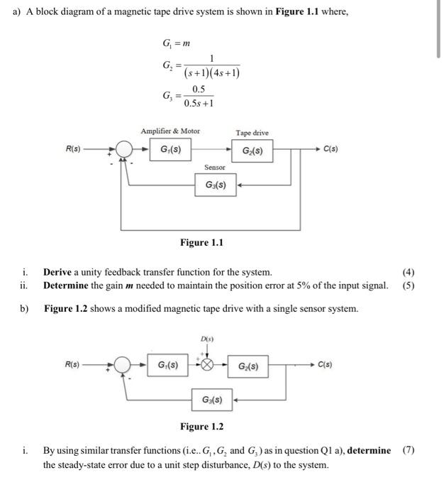
a) A block diagram of a magnetic tape drive system is shown in Figure where, i. Derive a unity feedback transfer function for the system. ii. Determine the gain needed to maintain the position error at of the input signal. b) Figure 1.2 shows a modified magnetic tape drive with a single sensor system. Figure i. By using similar transfer functions (i.e.. and ) as in question Q1 a), determine the steady-state error due to a unit step disturbance, to the system.