Home /
Expert Answers /
Electrical Engineering /
8-non-ideal-op-amp-realistic-circuit-the-inverting-amplifier-in-the-circuit-shown-has-an-inpu-pa148
(Solved): 8. Non-Ideal op amp (Realistic) circuit: The inverting amplifier in the circuit shown has an inpu ...
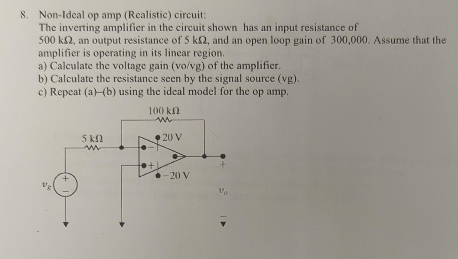
8. Non-Ideal op amp (Realistic) circuit: The inverting amplifier in the circuit shown has an input resistance of , an output resistance of , and an open loop gain of 300,000 . Assume that the amplifier is operating in its linear region. a) Calculate the voltage gain (vo/vg) of the amplifier. b) Calculate the resistance seen by the signal source (vg). c) Repeat (a)-(b) using the ideal model for the op amp.