Home /
Expert Answers /
Electrical Engineering /
4-design-of-digital-logic-gates-the-block-diagram-in-figure-b1-1-shows-a-mod-12-asynchronous-coun-pa903
(Solved): 4. Design of Digital Logic gates The block diagram in Figure B1.1 shows a Mod-12 asynchronous coun ...
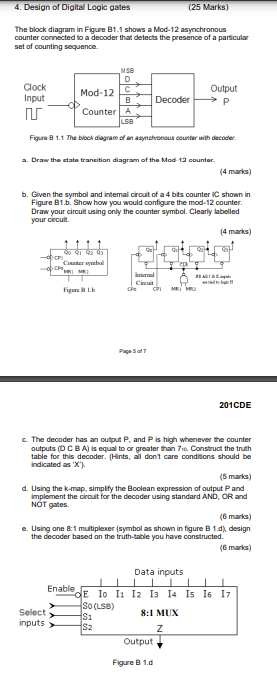
4. Design of Digital Logic gates The block diagram in Figure B1.1 shows a Mod-12 asynchronous counter connected to a decoder that detects the presence of a particular set of counting sequence. Clock Input ? MSB D Mod-12 C Counter A LSB Figure B 1.1 The block diagram of an asynchronous counter with decoder. a. Draw the state transition diagram of the Mod-12 counter. 90 91 92 93 Counter symbol (4 marks) b. Given the symbol and internal circuit of a 4 bits counter IC shown in Figure B1.b. Show how you would configure the mod-12 counter. Draw your circuit using only the counter symbol. Clearly labelled your circuit. (4 marks) Figure B 1.b Select inputs > (25 Marks) Decoder Internal circut Page 5 of 7 Enable GH Output P XAL MRI MR2 c. The decoder has an output P. and P is high whenever the counter outputs (D C B A) is equal to or greater than 710. Construct the truth table for this decoder. (Hints, all don't care conditions should be indicated as 'X'). Output Figure B 1.d (5 marks) d. Using the k-map, simplify the Boolean expression of output Pand implement the circuit for the decoder using standard AND, OR and NOT gates. 201CDE (6 marks) e. Using one 8:1 multiplexer (symbol as shown in figure B 1.d), design the decoder based on the truth-table you have constructed. (6 marks) Data inputs OE Io 11 12 13 14 15 16 17 So (LSB) 8:1 MUX S1 Sz