Home /
Expert Answers /
Electrical Engineering /
4-according-to-the-block-diagram-in-figure-1-you-will-design-an-op-amp-circuit-that-takes-an-inp-pa421
(Solved): 4. According to the block diagram in Figure 1, you will design an op-amp circuit that takes an inp ...
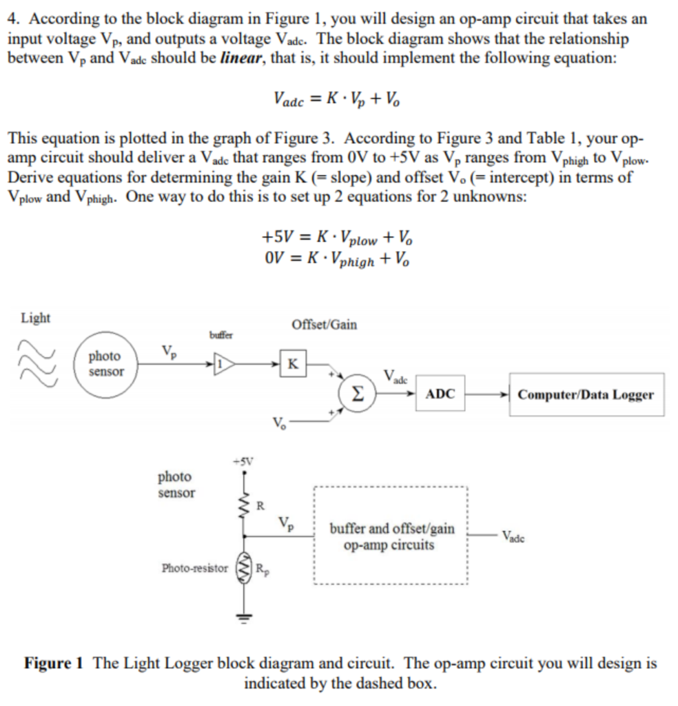
4. According to the block diagram in Figure 1, you will design an op-amp circuit that takes an input voltage \( V_{p} \), and outputs a voltage \( V_{\text {adc. }} \). The block diagram shows that the relationship between \( V_{p} \) and \( V_{\text {adc }} \) should be linear, that is, it should implement the following equation: \[ V_{a d c}=K \cdot V_{p}+V_{o} \] This equation is plotted in the graph of Figure 3. According to Figure 3 and Table 1, your opamp circuit should deliver a \( V_{\text {adc }} \) that ranges from \( 0 \mathrm{~V} \) to \( +5 \mathrm{~V} \) as \( \mathrm{V}_{\mathrm{p}} \) ranges from \( \mathrm{V}_{\text {phigh }} \) to \( \mathrm{V}_{\text {plow. }} \). Derive equations for determining the gain \( \mathrm{K} \) (= slope) and offset \( \mathrm{V}_{\mathrm{o}} \) (= intercept) in terms of \( V_{\text {plow }} \) and \( V_{\text {phigh. }} \) One way to do this is to set up 2 equations for 2 unknowns: \[ \begin{array}{l} +5 V=K \cdot V_{\text {plow }}+V_{o} \\ 0 V=K \cdot V_{\text {phigh }}+V_{o} \end{array} \] Figure 1 The Light Logger block diagram and circuit. The op-amp circuit you will design is indicated by the dashed box.
Expert Answer
The given two equations are: Subtracting equation (1) from equation (2), we get: Hence, since Vphigh > Vplow, K is negative i.e slope is negative. Substituting K in equation (2) to get offset voltage, Vo. Offset voltage, Vo is positive. Design of am