Home /
Expert Answers /
Electrical Engineering /
3-for-the-single-phase-half-wave-controlled-rectifier-shown-in-fig-3-9-thyristor-mathrm-t-1-pa942
(Solved): 3. For the single-phase half-wave controlled rectifier shown in Fig.3.9, thyristor \( \mathrm{T} 1 ...
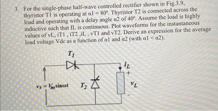
3. For the single-phase half-wave controlled rectifier shown in Fig.3.9, thyristor \( \mathrm{T} 1 \) is operating at \( \alpha 1=80^{\circ} \). Thyristor \( \mathrm{T} 2 \) is connected across the load and operating with a delay angle \( \alpha 2 \) of \( 40^{\circ} \). Assume the load is highly inductive such that \( \mathrm{IL} \) is continuous. Plot waveforms for the instantaneous values of \( v L \), iT1 , iT2, iL, vT1 and vT2. Derive an expression for the average load voltage \( V d c \) as a function of \( \alpha 1 \) and \( \alpha 2 \) (with \( \alpha 1<\alpha 2 \) ).