Home /
Expert Answers /
Civil Engineering /
1-figure-1-shows-the-plan-view-of-the-first-storey-of-a-4-storey-steel-building-column-mathr-pa349
(Solved): 1. Figure 1 shows the plan view of the first storey of a 4-storey steel building. Column \( \mathr ...
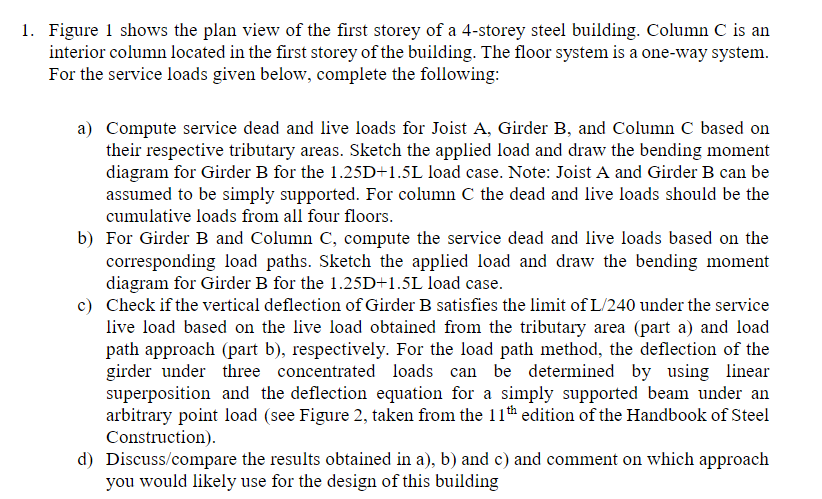
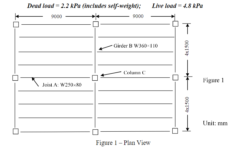
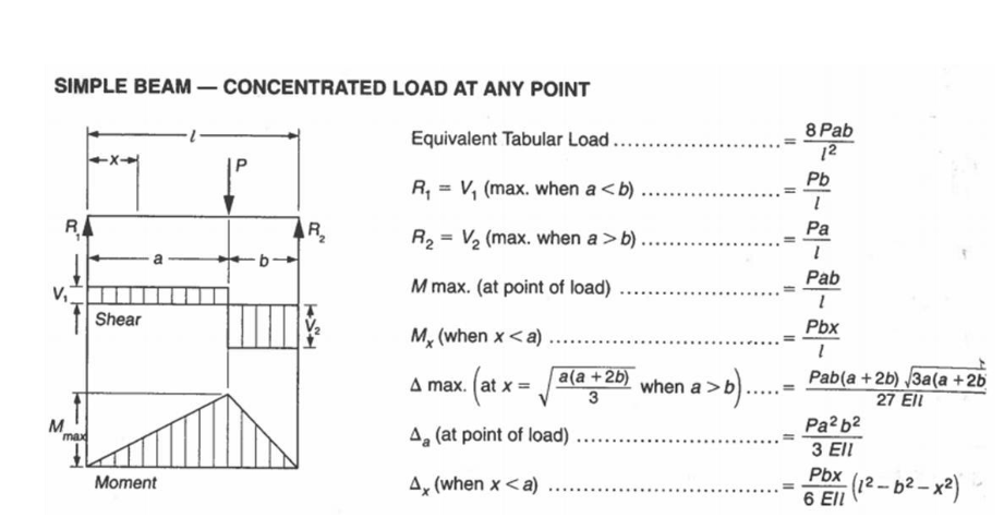
1. Figure 1 shows the plan view of the first storey of a 4-storey steel building. Column \( \mathrm{C} \) is an interior column located in the first storey of the building. The floor system is a one-way system. For the service loads given below, complete the following: a) Compute service dead and live loads for Joist A, Girder B, and Column C based on their respective tributary areas. Sketch the applied load and draw the bending moment diagram for Girder B for the 1.25D+1.5L load case. Note: Joist A and Girder B can be assumed to be simply supported. For column \( C \) the dead and live loads should be the cumulative loads from all four floors. b) For Girder B and Column C, compute the service dead and live loads based on the corresponding load paths. Sketch the applied load and draw the bending moment diagram for Girder B for the \( 1.25 \mathrm{D}+1.5 \mathrm{~L} \) load case. c) Check if the vertical deflection of Girder B satisfies the limit of L/240 under the service live load based on the live load obtained from the tributary area (part a) and load path approach (part b), respectively. For the load path method, the deflection of the girder under three concentrated loads can be determined by using linear superposition and the deflection equation for a simply supported beam under an arbitrary point load (see Figure 2, taken from the \( 11^{\text {th }} \) edition of the Handbook of Steel Construction). d) Discuss/compare the results obtained in a), b) and c) and comment on which approach you would likely use for the design of this building
Figure 1 - Plan View
SIMPLE BEAM - CONCENTRATED LOAD AT ANY POINT Equivalent Tabular Load \( \ldots \ldots \ldots \ldots \ldots \ldots=\frac{8 P a b}{l^{2}} \) \( R_{1}=V_{1} \) (max. when \( \left.ab \) ) \( \ldots \ldots \ldots \ldots \ldots \ldots=\frac{P a}{l} \) \( M \) max. (at point of load) ................... \( =\frac{P a b}{l} \) \( \Delta \max .\left(a \mathrm{t} x=\sqrt{\frac{a(a+2 b)}{3}}\right. \) when \( \left.a>b\right) \ldots . .=\frac{P a b(a}{} \) \( \Delta_{x}( \) when \( x
Expert Answer
Solution :: Dead load CD) 2 .5kPa Line load (L) 4.8 Kla width -A (a) OL on joist A of jost - - 2x Tributary 2.5x (2.0+2.0)=10 & kN/m 4.8×(2.0+2.0)=19.